How to Build a PID Temperature Controller: A Comprehensive Guide
Learn how to build a PID temperature controller with this detailed guide. From selecting components to programming and tuning, we cover everything you need to know for precise temperature control.
1. PID Temperature Controllers
A Proportional-Integral-Derivative (PID) temperature controller is an advanced feedback mechanism widely employed across industries to maintain precise temperature regulation. Used primarily as process temperature controls for maintaining product quality, safety, and efficiency - PID controllers continuously adjust output according to any deviation between desired setpoint and actual temperatures, guaranteeing stable yet precise regulation.
2. Components and Tools Needed
To construct a PID temperature controller, the following items will be necessary.
* Heating Element: Such as a heating pad or resistive heater.
* Power Source: To power both the heating element and microcontroller.
* Breadboard and Jumper Wires: These materials allow prototyping the circuit.
* Soldering Iron and Solder: For creating secure connections.
* Multimeter: Use this for measuring and diagnosing circuit issues.
3. Design and Assemble of Circuits
Circuit design and assembly involve creating a schematic diagram and following step-by-step instructions in order to connect all the necessary components.
This schematic shows how to connect a temperature sensor directly into an analog input on your microcontroller.
* Connect the SSR to one of the digital output pins on the microcontroller.
* Connect the heating element directly to an SSR.
* Verify the power supply is correctly connected to both the microcontroller and heating element.
1. Assembly Instructions:* Arrange the components on a breadboard according to their positions on the schematic.
* To make connections quickly and safely, utilize jumper wires.
Solder all connections if creating a permanent setup.
4. Programming a microcontrolleR
entails writing and uploading code which implements PID algorithm. Here is an outline of steps involved.
PID Algorithm (Proportional Integral and Derivative Algorithm): These algorithms use proportional, integral, and derivative terms to calculate control outputs.
The proportional term adjusts output proportionally to any current error.
The integral term adjusts output according to any errors accumulated over time.
The derivative term adjusts output based on the rate of change of error.
Snippet Code Example for PID Library Installation and Variable Definition -- MyPID(&Input,&Output,Kp, Ki, Kd and Direct);
5. Void setup(); mes
MyPID.SetMode(AUTOMATIC); contul loop()
Input=analogRead(A0); Set Point 100 for temperature sensor Input, compute output through myPID.Compute(), control heating element by analogWrite(9, Output); Before uploading my code
* To connect a microcontroller to your computer using USB, connect its cable.
* Launch the Arduino IDE or any suitable development environment.
* Use an integrated development environment (IDE) to write or paste code directly.
Upload the code onto a microcontroller.
6. Tuning PID Parameters
Tuning the PID parameters (Kp, Ki and Kd) to achieve optimal performance is absolutely key for reaching peak results. There are multiple techniques for doing so; here are just a few methods:
* Manual Tuning: Involves manually tuning parameters until desired performance is realized, usually through trial-and-error adjustments based on understanding system dynamics.
* Ziegler-Nichols Method: This popular heuristic tuning approach to PID parameters involves setting integral and derivative gains to zero before increasing proportional gain until your system oscillates at constant amplitude.
* Software Tools: Modern PID controllers feature built-in software tools to facilitate tuning the process automatically and determine optimal parameters based on how the system responds. These advanced algorithms use AI algorithms to determine optimal values.
Correct tuning ensures that a PID controller delivers rapid responses with minimal overshoot or steady-state error.
7. Testing and Calibration
Testing and calibrating the PID temperature controller requires verifying its performance while making any required adjustments to ensure maximum accuracy.
1. Ongoing Testing Procedures: * Connect both temperature sensor and heating element to PID controller for testing purposes.
* Enter a desired temperature setting, and observe its response from your system.
*Utilise a multimeter to assess actual temperature versus setpoint temperature.
Wife's Technique for PID Calibration: (TIP: for more details. ) * Modulate PID parameters so as to minimize differences between setpoint temperature and actual temperature, by adjusting PID parameters accordingly.
* Use calibration tools or software to fine-tune sensor readings.
PID temperature controllers have become an essential tool across numerous industries: they're found everywhere from manufacturing plants and laboratories, to restaurants.
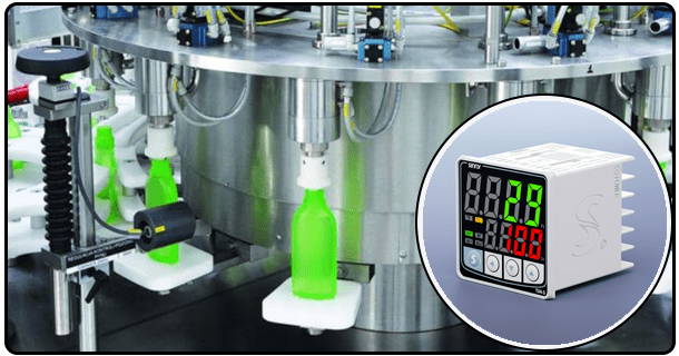
* Industrial Applications: PID controllers play an essential role in chemical processing by maintaining precise temperatures during reactions that ensure product quality and safety, and also in food and beverage industries where they regulate temperatures during cooking, fermentation and storage processes.
* Commercial Applications: HVAC (Heating, Ventilation and Air Conditioning) systems use PID controllers to maintain comfortable indoor temperatures while refrigerator systems depend on them to store products at their optimal temperatures.
* Laboratory and Research Applications: PID controllers are commonly utilized within laboratories for maintaining stable temperatures for experiments and research projects using incubators, ovens, or any other piece of equipment to conduct experiments or studies.
8. Troubleshooting and Maintenance
Maintaining and troubleshooting a PID temperature controller involves identifying common problems as well as performing ongoing maintenance for optimal reliability.
Common Issues and Solutions: * Overshoot and Oscillations: Adjust the PID parameters accordingly to reduce overshoot and stabilize your system.
Sensor Errors: Before connecting and calibrating temperature sensors, verify their proper installation and connection.
Output Issues: Verify all connections and functionality of SSR and heating element components.
Regular Maintenance Tips: * To avoid malfunction, regularly test and calibrate the temperature sensor.
Inspect all connections and components for signs of wear or damage.
When necessary, update the microcontroller firmware and software as required.
9. Conclusion
Results Building a PID temperature controller involves selecting and assembling appropriate components, designing and programming the microcontroller, tuning PID parameters as specified, testing and calibrating system to achieve reliability and effectiveness for various applications. By following these steps properly tuned and maintained units can deliver long term reliability without interruption in performance or upkeep costs. To guarantee optimal results and long term dependability.
- How to Determine PID Controller Parameters: A Comprehensive Guide
- How Does a PID Temperature Controller Operate?


