


The Step-byStep Guide to Setting a PID Controller
Our step-by-step tutorial will show you how to install a PID controller. Find out the required components, how to wire them, and some tuning tips.

1. Introduction
Required Components
You will require the following parts to set up a temperature PID controller:
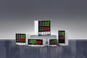
PID controller: Main unit which processes input and adjusts output.
Temperature sensor A thermocouple (or RTD) to measure actual temperature.
Power supply: Supplies the required power for the PID Controller and other components.
Relay A solid-state or mechanical relay that controls the heating/cooling system.
Heat/Cooling device A device which provides heat or cooling when required.
2. How to wire the PID controller
Connecting the Temperature sensor: Attaching the temperature sensors to the input terminals of the PID controller. Verify that the type of sensor matches the configuration on the PID Controller.
Connecting the Power Supply: Follow the wiring diagram to connect the power supply with the PID controller. Check the current and voltage ratings twice to avoid damage.
Connect Relay Attach the relay terminals of the PID controller. Verify that the temperature and voltage requirements are compatible with the relay.
3. Initial Configuration
Turn On the PID Control Once the connections have been made, turn on the controller.
Select the Type of Sensor Enter the Setup menu and choose the type (e.g. thermocouple type RTD or type K).
Enter desired temperature setting: Input the desired temperature into the PID control. The target temperature is what the system will try to maintain.
Proportional (P): This determines the amount of output change in response to current error. Adjust the gain proportionally until you see the system oscillating. After oscillations have been observed, reduce the value of proportional gain by half to get a more stable response.
Integer (I) : This is the integral gain that determines the amount of output change in response to the cumulative error. The integral gain can be increased in small steps until the system is able to respond adequately to the changes in setpoint.
Derivative: This is the derivative gain, which determines the amount the output will change in response to changes in the error rate. The derivative gain can be adjusted to stabilize and dampen the response of the system.
4. Troubleshooting and Testing
Check the System After tuning PID parameters and testing the system, ensure that it keeps the temperature desired. Watch the response of the system and adjust if needed.
Troubleshoot Issues If your system is not performing as you expect, look for problems with the wiring, sensor settings, or PID. Verify that all sensors are calibrated correctly and the connections on each sensor are tight.

5. Final Install
Installing the PID Relay and Controller Once your system has been tested, and is working correctly, you can install the relay and PID controller in the project box. The components are protected from moisture and dust.
Insulate and Secure all Connections Ensure that electrical connections are properly insulated. To prevent electrical hazards, and to ensure the stability of your system, it is important that you ground properly.
- The Complete Guide to PID Temperature Control
- Comprehensive guide to building a PID temperature controller