


Comprehensive guide to building a PID temperature controller
Discover the PID temperature controller components, their circuit design, programming and assembly, as well as its applications.

1. Introduction
It is rewarding to build a PID controller that you can customize to meet your needs. The PID controller uses Proportional Integral and Derivative Control elements in order to regulate temperature precisely. This article is a guide to building a PID controller. It includes the components needed, the circuit design, programming and assembly.
2. Tools and Components Required
You will require the following tools and components to build a PID Temperature Controller:
Components:
Microcontroller (e.g., Arduino)
Temperature Sensor (e.g. thermocouple PT100).
Heating element
Solid state relays (SSRs)
Electricity supply
Display (e.g. LCD screen)
Connecting wires
As required, resistors and capacitors
Tools:
Sellering iron
Multimeter
Jumper and breadboard wires
The screwdriver and the pliers
Computer equipped with Arduino IDE or other software relevant
3. Circuit Design
It is important to create a circuit diagram, and then connect the various components. These steps will help you:
Diagram of
Start by sketching a circuit diagram, showing all the connections between each component.
Connection for Temperature Sensor:
Connect the sensor to the controller. Connect the output of the temperature sensor to an analog pin on an Arduino.
SSR and Heating Element:
The output terminals on the SSR (solid-state relay) are the best place to connect the heating element.
Connect one of the pins for digital output on the microcontroller to the SSR control terminals.
Power Source:
Make sure that your power supply has the appropriate rating for the heater element, and any other component. Connect the power supply to the microcontroller as well as the heating element.
Display:
Connect the LCD to the microcontroller according to manufacturer's instructions. You can monitor temperature and the controller status.
4. Microcontroller Programming
The PID algorithm is written and uploaded to the microcontroller. These steps are to be followed:
PID algorithm:
Create a PID algorithm to read the sensor's temperature data, calculate the error and then adjust the output of the heating element accordingly.
To simplify the process, you can use PID libraries already available (e.g. Arduino PID Library).
Uploading Code:
Use the Arduino IDE software to upload the PID code onto the microcontroller.
Verify that the code contains functions to read the sensor data and compute the PID output as well as control the heating element.
5. PID Parameter Tuning:
To achieve the best performance, you can tune PID parameters Kp, Ki and Kd. It may take some trial and error before you find the right values.
Assembly of Hardware
Assembly of the hardware requires arranging components on a printed circuit board or breadboard and connecting them. These are the steps to follow:
Breadboard Assembly:
Place the components onto a breadboard, and use jumper wires to make a temporary connection.
Check that the circuit is working properly.
Soldering:
Transfer the components onto a PCB once the circuit has been tested and validated. This will allow for a permanent installation.
To ensure electrical connection reliability, solder the connectors to the component.
Testing:
Test the system after assembling all the components to make sure that it operates according to expectations.
Check that temperature is accurate, and the heating element reacts when the temperature changes.
Testing and calibrating the PID controller
The PID controller must be calibrated and tested to ensure precise temperature control. These steps will help you:
Initial calibration:
To ensure accuracy, calibrate the sensor at first.
Check that the output of the sensor corresponds with the temperature.
Test the controller:
Set a temperature target (setpoint), and observe the response of the PID.
Check the PID controller's temperature output and temperature readings to make sure it is maintaining the set temperature.
Fine-Tuning:
To improve controller performance, adjust the PID parameter (Kp Ki Kd).
Find the settings which achieve the balance of responsiveness and stabilty by trial and error.
Use cases and Applications
You can tailor a PID controller to suit different applications by building your own. Among the many practical applications are:
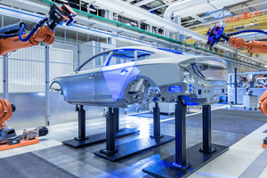
Industrial Processes:
PID temperature controllers are used to control industrial processes, such as food and chemical processing.
HVAC Systemsa
Use the PID control in HVAC systems to achieve comfortable temperatures.
Laboratory equipment:
You can use the PID controller to control temperature in lab equipment like incubators, water baths and ovens.
Projects for DIY:
Use the PID control in DIY projects such as 3D heated bed printers, home brewing and climate control.

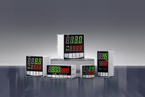
6. PID controller
project is an educational and rewarding one that will allow you to regulate temperature precisely in a variety of applications. You can follow the instructions in this article to design the circuit and program the microcontroller. Then, you can assemble the hardware. Finally, calibrate the controller for optimal performance. A custom PID control offers precision, reliability and versatility. It is a useful tool both for industrial use and personal.
- The Step-byStep Guide to Setting a PID Controller
- Components of PID temperature controllers: Principles and applications