How to Implement a PID Controller: Step-by-Step Guide for Precise Control
Learn how to implement a PID controller with our comprehensive guide. Follow step-by-step instructions to achieve precise control for your applications. Ideal for industrial and home automation systems.
1.Introduction
PID (Proportional-Integral-Derivative) controllers are essential parts of various control systems, helping maintain desired output by making adjustments based on feedback and controlling inputs according to feedback loops. This guide offers comprehensive overview on implementing PID controllers precisely to fit your applications while guaranteeing stable, precise control for manufacturing, robotics and process control industries alike. PID controllers have become ubiquitous due to their stability and accuracy - these types of control solutions have even found use across industries like aviation!
2.Understanding PID Control
PID control utilizes three components that work in unison: Proportional, Integral and Derivative controls. Each of these controls addresses different aspects of the controlling process: Proportional (proportionality), Integral and Derivative controls are interwoven throughout.
Integral (I): This component accumulates past errors to help ensure the system reaches the setpoint by eliminating steady-state errors and reaching equilibrium.
* Derivative (D): This component anticipates future errors based on their rate of change, providing a damping effect and helping prevent overshoot and oscillations.
The PID equation can be mathematically represented as follows: For each time period: U(t)=K_p e(t), + K_i inte e(t), and K_d infrac dde(t).
PID control offers many advantages over alternative approaches for maintaining stability: faster response times and reduced oscillations are just some. It has proven itself time after time with regard to stability issues as well as reduced oscillations over other methods of regulation.
3.Components and Tools Needed
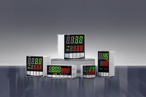
To implement a PID controller, the following components and tools will be necessary: * PID Controller Hardware or Software: Depending on your application requirements, dedicated PID controller devices or implementation of its algorithm in software may be required.
* Sensors: These devices monitor process variables like temperature, pressure or speed to provide feedback to a PID controller.
* Actuators: Actuators (such as motors and valves ) carry out the control actions defined by PID controller.
*Microcontroller or PLC (Programmable Logic Controller): These devices process sensor data and implement PID algorithms for proper operation of systems.
* Wiring tools and materials: Such as wires, connectors and insulation materials used for making electrical connections.
4.Designing the PID Controller
Step One in Designing the PID Controller
Define Your Target Outcome/Setpoint
Set goals that can be clearly measured against, such as maintaining temperature or speed levels within your system. Your control objective must also be easily understandable to those outside.
Step Two: Select Your PID Controller
To select your controller, either hardware- or software-based PID models should be considered. Hardware models act independently while software versions can be integrated onto microcontrollers or PLCs for implementation.
Step 3: Setup PID Parameters To set initial values for Proportional, Integral and Derivative gains - these will need to be tuned later for optimal performance.
5.Implementing a PID Controller
Step 1: Connect Sensors and Actuators WIRE the sensors to the input terminals and actuators to output terminals of your PID controller ensuring all connections are secure and insulated appropriately.
Step 2: Programming the Microcontroller or PLC
Write code that can read sensor data, compute PID output and control actuators. Be sure that this code includes real-time processing capabilities with real PID algorithm functionality and realtime data handling capabilities.
Step 3: Integrating PID Algorithm
To complete step 3, integrate a PID algorithm in the control loop by continuously reading sensor data, computing errors, and making adjustments based on PID equation.
6.Tuning Your PID Controller
Tuning PID parameters is crucial to reaching optimal performance. There are various approaches available for tuning:
* Ziegler-Nichols Method: A heuristic tuning approach in which Integral, Derivative and Proportional gains are set equal and increased until system oscillation begins; then using its ultimate gain value and oscillation period period as input parameters to calculate PID parameters.
Trial-and-Error Methodology: Manually adjusting PID parameters while monitoring their system response is another approach which may produce positive outcomes, however this requires patience and experience for optimal outcomes.
* Software Tools: PID controllers may include software tools to assist with tuning processes, making it simpler and faster to achieve optimal performance.
Testing and Validation
Step 1: Simulate the Control System
Use simulation tools to run through simulations of your PID controller before it is actually deployed into an actual system, to detect potential issues early and make necessary adjustments without risk to physical systems.
Step Two: Conduct Real-World Testing
To validate a PID controller within its actual environment and monitor how it responds against set criteria.
Step 3: Monitor and Adjust
Continue monitoring the system while making any necessary modifications to its PID parameters as part of regular maintenance and calibration efforts to keep everything operating efficiently. Regular system check-ups will keep things running smoothly.
7.Troubleshooting Common Issues
Implementing a PID controller may present several unique obstacles and difficulties; here are some key problems and their possible resolutions:
* Oscillations: If the system oscillates too frequently, its Proportional Gain may be too high; to reduce oscillations further reduce this gain or increase Derivative gain to dampen oscillations.
* Slow Response: If your system responds too slowly, its Integral gain might be too low - increasing this figure should speed up response times and quicken response.
* Steady-State Error: If the system doesn't reach the setpoint, its integral gain might be too low - in such instances increasing it should reduce steady-state errors and correct them.
- How to Program a PID Controller: A Comprehensive Guide.
- How to Wire a PID Controller: Step-by-Step Guide for Precise Temperature Control


