


Comprehensive Guide to PID Temperature Controller Schematic
Learn how to design, program, and implement a PID temperature controller with our comprehensive guide. Understand key components, schematic design, programming, and applications.
1. Introduction
PID controllers, which stand for Proportional-Integral-Derivative controllers, are integral components in many industrial and consumer applications. They are used to maintain a desired setpoint by adjusting control variables, ensuring processes run smoothly and efficiently. Temperature control is one of the most common applications of PID controllers, as precise temperature regulation is crucial in numerous industries, including manufacturing, food processing, and laboratory environments. This article aims to provide a comprehensive guide on PID temperature controller schematics, elucidating their components, design, programming, and applications.
2. What is a PID Temperature Controller?
A PID temperature controller is a sophisticated feedback mechanism that continuously calculates an error value as the difference between a desired setpoint and a measured process variable, in this case, temperature. The controller then applies a correction based on proportional, integral, and derivative terms, which give the controller its name. These controllers consist of three fundamental components: the Proportional term, which responds proportionally to the current error; the Integral term, which accounts for past errors; and the Derivative term, which predicts future errors based on the rate of change. Together, these terms enable the PID controller to maintain an optimal temperature by minimizing the deviation from the setpoint.
3. Components of a PID Temperature Controller Schematic
The main components of a PID temperature controller schematic include:
·
Temperature Sensor: Devices such as thermocouples or resistance temperature detectors (RTDs) are used to measure the process temperature.
·
·
Microcontroller or PID Controller Unit: This is the brain of the controller, where the PID algorithm is implemented. Common microcontrollers include the Arduino, Raspberry Pi, and dedicated PID controller chips.
·
·
Heating Element: This could be a resistive heater, a thermoelectric cooler, or any other device used to regulate the temperature.
·
·
Solid State Relay (SSR): An SSR is used to switch the heating element on and off in response to the controller's output.
·
·
Power Supply: This provides the necessary electrical power to the controller and the heating element.
·
·
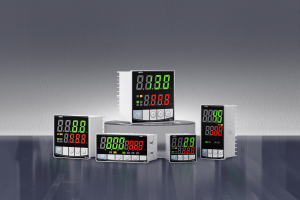
Display and User Interface: These components allow users to set the desired temperature and monitor the current temperature and controller status.
·
4. Designing the Schematic
Designing a PID temperature controller schematic involves several steps:
1.
Connecting the Temperature Sensor: The sensor is connected to the input of the microcontroller or PID unit. It converts the physical temperature into an electrical signal that can be read by the controller.
2.
3.
Integrating the Microcontroller: The microcontroller is programmed to execute the PID algorithm. It takes the temperature sensor's input and calculates the necessary control action.
4.
5.
Connecting the Heating Element and SSR: The output of the microcontroller is connected to the SSR, which switches the heating element on and off. The SSR provides isolation between the high-power heating element and the low-power microcontroller.
6.
7.
Power Supply Considerations: Ensure that the power supply is adequate for both the controller and the heating element. Use appropriate voltage regulators and protective components to ensure safety.
8.
9.
Adding the Display and User Interface: Implement a display to show the current temperature and setpoint. The user interface allows users to set the desired temperature and adjust other parameters.
10.
Below is an example schematic diagram for reference:
5. Programming the PID Controller
Programming a PID controller involves writing code that implements the PID algorithm and uploading it to the microcontroller. Here is a step-by-step guide:
1.
Overview of PID Algorithm: The PID algorithm computes the control action as a sum of the proportional, integral, and derivative terms. The control action is then used to adjust the output to minimize the error.
2.
3.
Writing and Uploading Code: Write code in a suitable programming language (e.g., C++ for Arduino) to implement the PID algorithm. Upload the code to the microcontroller using an appropriate development environment.
4.
5.
Tuning the PID Parameters: Adjust the proportional, integral, and derivative parameters to achieve stable and efficient temperature control. This process, known as tuning, involves trial and error and may require some expertise.
6.
7.
Example Code Snippets: Here is a basic example of a PID control loop in Arduino:
6. Testing and Troubleshooting
After designing and programming the PID controller, it is essential to test and troubleshoot the system:
1.
Initial Setup and Testing: Power up the system and verify that the temperature readings are accurate. Adjust the setpoint and observe the controller's response.
2.
3.
Common Issues and Solutions: If the controller exhibits instability (e.g., oscillations), adjust the PID parameters. Ensure all connections are secure and the power supply is adequate.
4.
5.
Fine-Tuning the PID Parameters: Fine-tune the PID parameters to achieve the desired response. This may involve iterative adjustments and testing.
7. Applications of PID Temperature Controllers
PID temperature controllers have a wide range of applications, including:
·
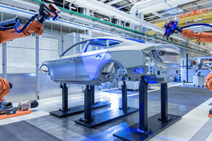
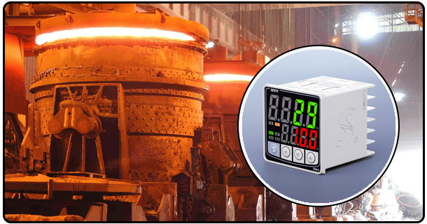
Industrial Applications: Maintaining precise temperature control in manufacturing processes, such as injection molding and chemical reactions.
·
·
Home Automation: Regulating temperatures in smart home systems, including HVAC and oven controls.
·
·
Laboratory Equipment: Ensuring stable temperature conditions in scientific experiments and equipment like incubators and water baths.
·
·
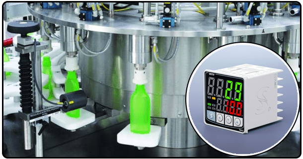
Other Use Cases: Controlling temperatures in food processing, brewing, and other specialized applications.
·
8. Conclusion
In summary, PID temperature controllers are vital in ensuring precise temperature control in various applications. By understanding their components, designing an appropriate schematic, programming the controller, and fine-tuning the parameters, one can achieve optimal temperature regulation. As technology advances, the future of PID temperature controllers promises even more sophisticated and efficient solutions.
- Universal PID temperature control controller
- PID Temperature Controller with SSR Output: Comprehensive Guide & Applications